1/6
Spreadsheets
Fixed Steel Base Plate Design Excel Calculator (AISC 360-22 & AISC Design Guide 1 LRFD)
39 $
Ask AI
What's Included
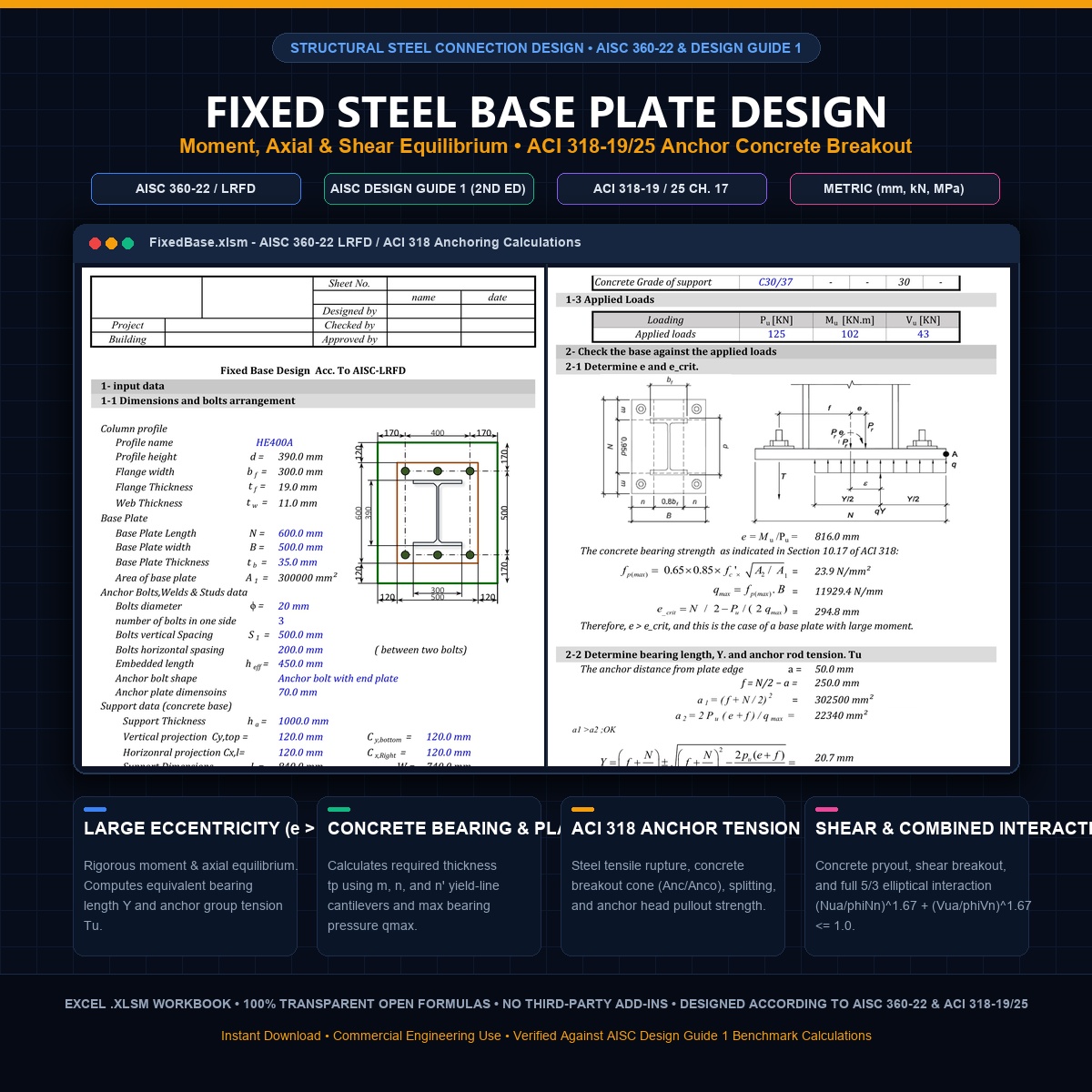
Structural steel column base plate design spreadsheet evaluating axial compression/tension, major-axis bending moment, and shear force in accordance with AISC 360-22 (LRFD) and AISC Design Guide 1 (2nd Edition). Includes complete concrete anchorage qualification per ACI 318-19 and ACI 318-25 Chapter 17.
• Major-Axis Moment & Axial Equilibrium: Automated classification for Small Eccentricity (Case I, bearing only) and Large Eccentricity (Case II, anchor rod tension and concrete compression).
• Concrete Bearing & Thickness Optimization: Yield-line analysis using cantilever parameters m, n, and n’ to establish required plate thickness tp against maximum bearing stress qmax.
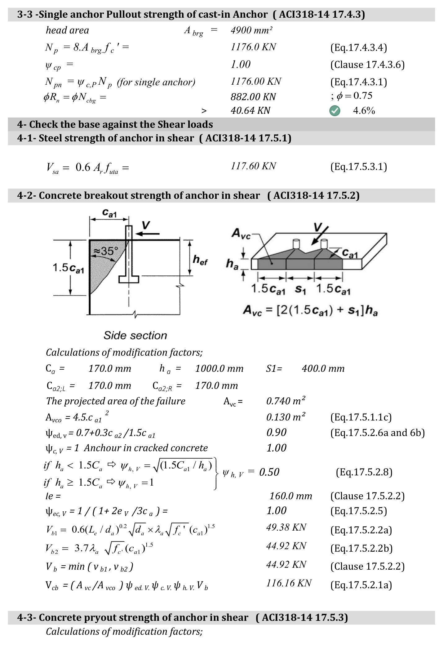
• Anchor Rod Tension Checks (ACI 318 Ch. 17): Steel tensile rupture phi*Nsa, full concrete breakout prism phi*Ncbg with edge distance and spacing factors, and head pullout phi*Npn.
• Shear Transfer Mechanisms: Steel shear rupture phi*Vsa, concrete shear breakout phi*Vcbg, and concrete pryout phi*Vcpg.
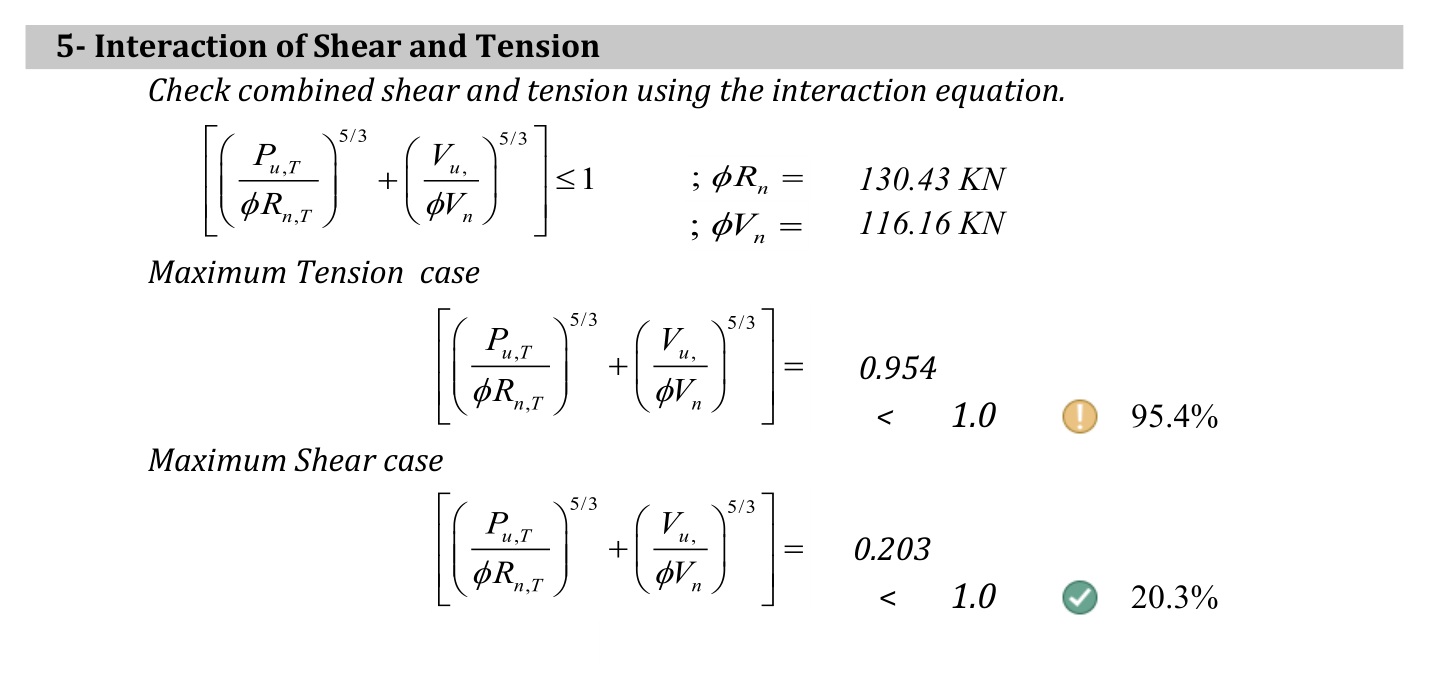
• Combined Interaction: Tri-linear and 5/3 elliptical interaction checks (Nua/phi*Nn)^1.67 + (Vua/phi*Vn)^1.67 <= 1.0 for concurrent maximum tension and maximum shear conditions.
• Cross-Section Library: Integrated European and American wide-flange column profile databases with open, transparent Excel formulas.
Instant Digital Access
Direct file download immediately after checkout. Access anytime under My Account.
Verified & Standard Compliant
Spreadsheets, tools, and code templates are fully tested for technical accuracy.
Dedicated Support
Direct technical assistance via Telegram @hungthinhvn or Email hangchat.xyz@gmail.com
Product Description
1. Technical Overview & Design Standards
This engineering design workbook calculates structural steel column base plates subjected to concurrent axial load (compression or uplift tension), major-axis flexural moment, and transverse shear force. The computational formulation strictly implements the Load and Resistance Factor Design (LRFD) methodology codified in AISC 360-22 (Specification for Structural Steel Buildings) and the design procedures defined in AISC Design Guide 1 (2nd Edition): Base Plate and Anchor Rod Design. Concrete foundation capacity and anchor embedment verifications are evaluated in accordance with ACI 318-19 / ACI 318-25 Chapter 17 (Anchoring to Concrete).
Steel Standard: AISC 360-22 LRFD
Design Reference: AISC Design Guide 1 (2nd Ed.)
Concrete Code: ACI 318-19 / ACI 318-25 Ch. 17
Units: Metric (kN, mm, MPa)
Format: Excel .XLSM (Active Macro Library)
Formula Transparency: 100% Native Unprotected
2. Input Geometry, Profile Library & Anchor Arrangement
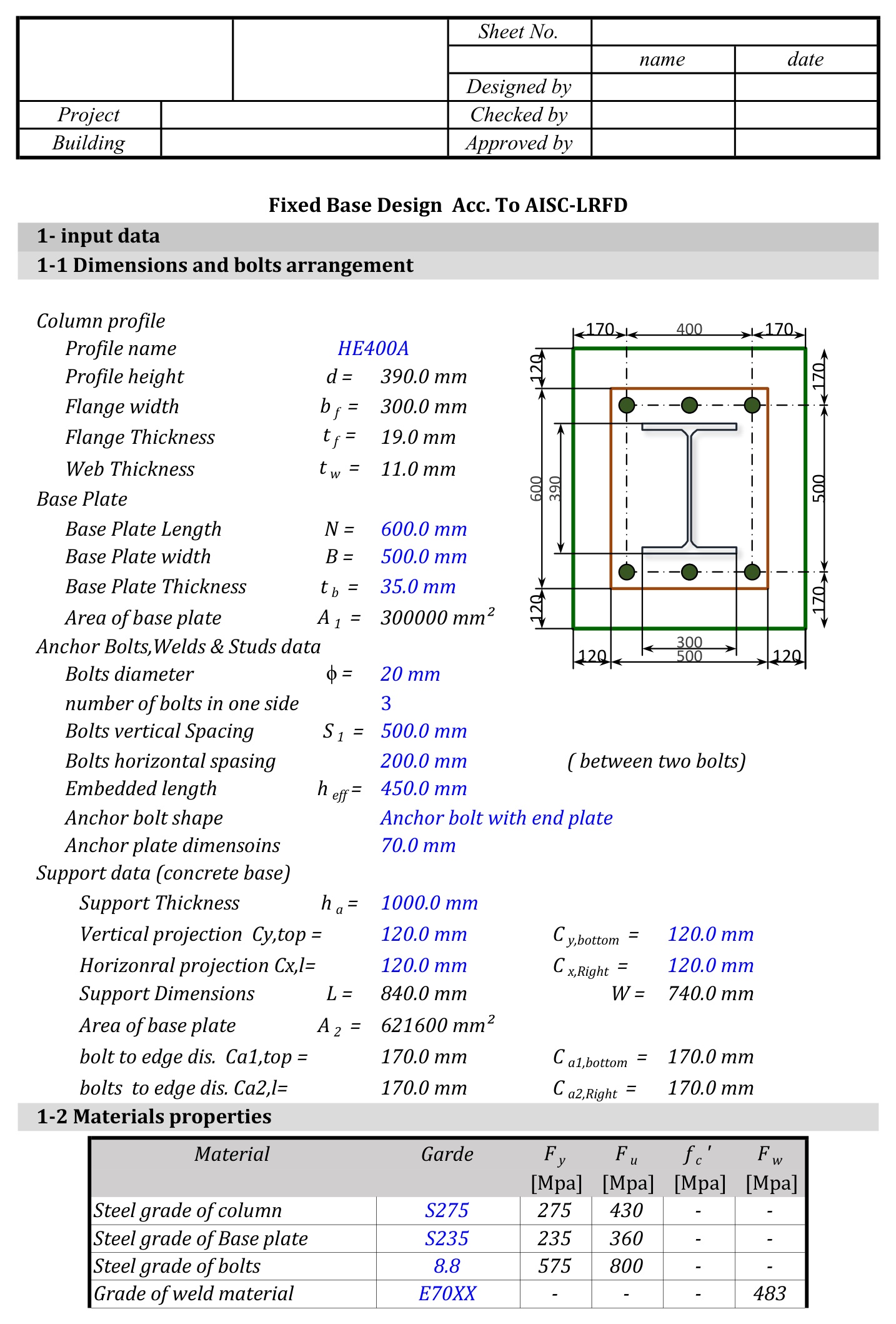
The workbook provides automated section property lookup from integrated steel section tables (including European HE/IPE profiles and American W-shapes). Dimensions for column height (d), flange width (bf), flange thickness (tf), and web thickness (tw) are populated dynamically upon section selection. Base plate planar dimensions (Length N, Width B, Thickness tb) and anchor bolt patterns are user-definable with real-time edge distance validation.
| Parameter | Symbol | Unit | Description & Governing Standard |
|---|---|---|---|
| Column Section | d, bf, tf, tw | mm | Structural wide-flange column profile selected from built-in section library. |
| Base Plate Geometry | N, B, tb | mm | Plate length parallel to moment axis (N), width (B), and preliminary thickness (tb). |
| Anchor Bolt Array | phi, n_b, S1, S2 | mm, qty | Bolt diameter, number of rods per side, vertical spacing (S1), and transverse spacing (S2). |
| Edge Distances | Ca1, Ca2 | mm | Concrete foundation edge distances along parallel and perpendicular loading axes. |
| Material Strengths | Fy, f’c, Fub | MPa | Yield strength of plate/column, concrete cylinder compressive strength, and anchor tensile grade. |
3. Moment-Axial Equilibrium & Large Eccentricity Formulation
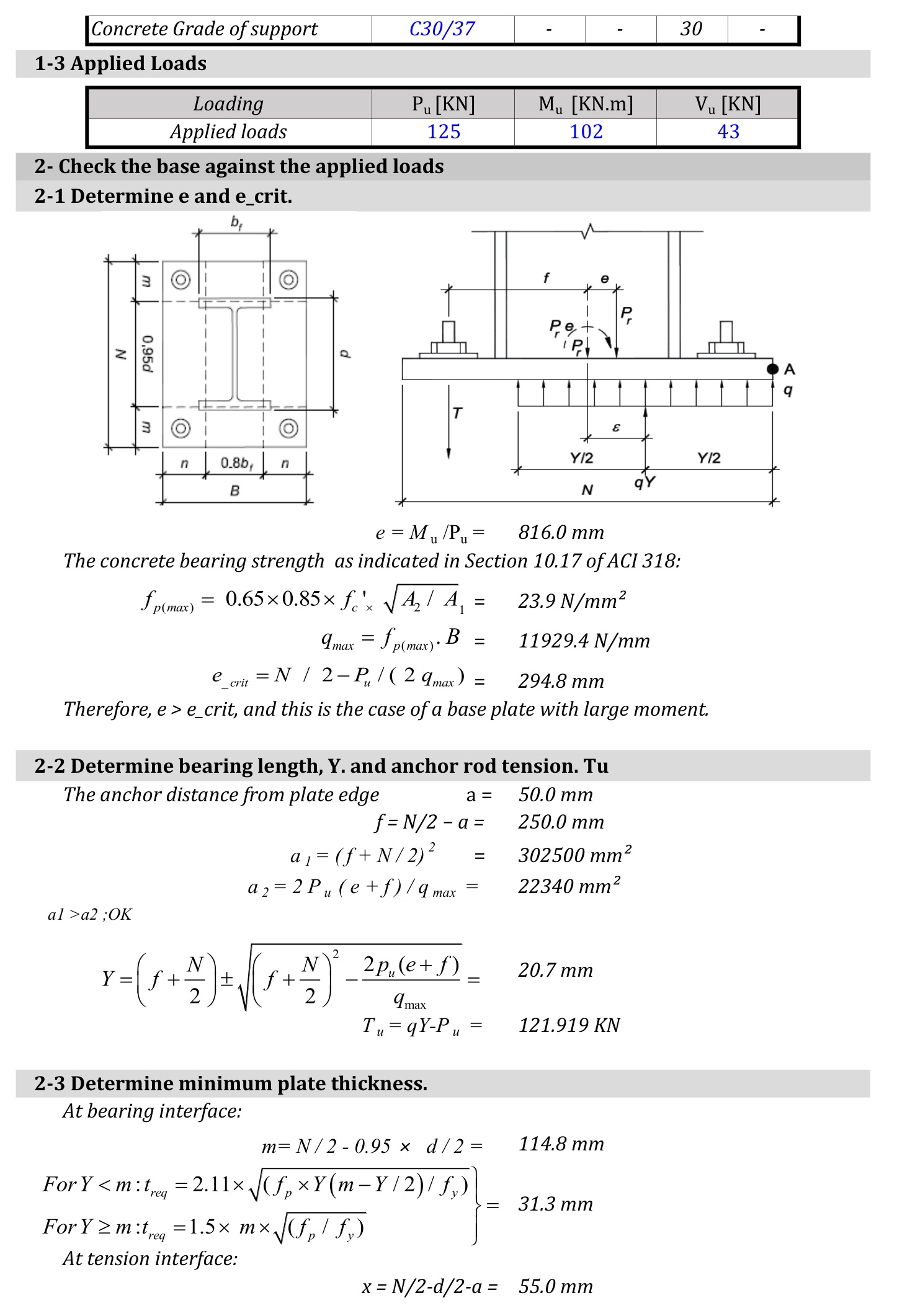
The eccentricity of the applied resultant axial force is calculated as e = Mu / Pu. The workbook evaluates the critical eccentricity threshold (e_crit) in accordance with AISC Design Guide 1 Section 3.4. When e > e_crit, internal strain compatibility generates tensile force in the windward anchor rods and non-linear bearing compression beneath the leeward base plate toe:
Key Equilibrium Governing Equations:
Critical Eccentricity: e_crit = N / 2 – Pu / (2 * q_max * B)
Concrete Bearing Stress Limit: q_max = phi_c * 0.85 * f’c * sqrt(A2 / A1) <= phi_c * 1.7 * f’c (phi_c = 0.65)
Bearing Length Solution: Y = (f + N/2) – sqrt((f + N/2)^2 – (2 * Pu * (e + f)) / (q_max * B))
Anchor Group Tension: Tu = q_max * B * Y – Pu
Cantilever Arms: m = (N – 0.95 * d) / 2, n = (B – 0.80 * bf) / 2, n’ = sqrt(d * bf) / 4
Required Thickness: t_req = max(m, n, lambda * n’) * sqrt((2 * Pu) / (0.90 * Fy * B * Y))
4. Anchor Rod Tensile Qualification (ACI 318 Ch. 17)
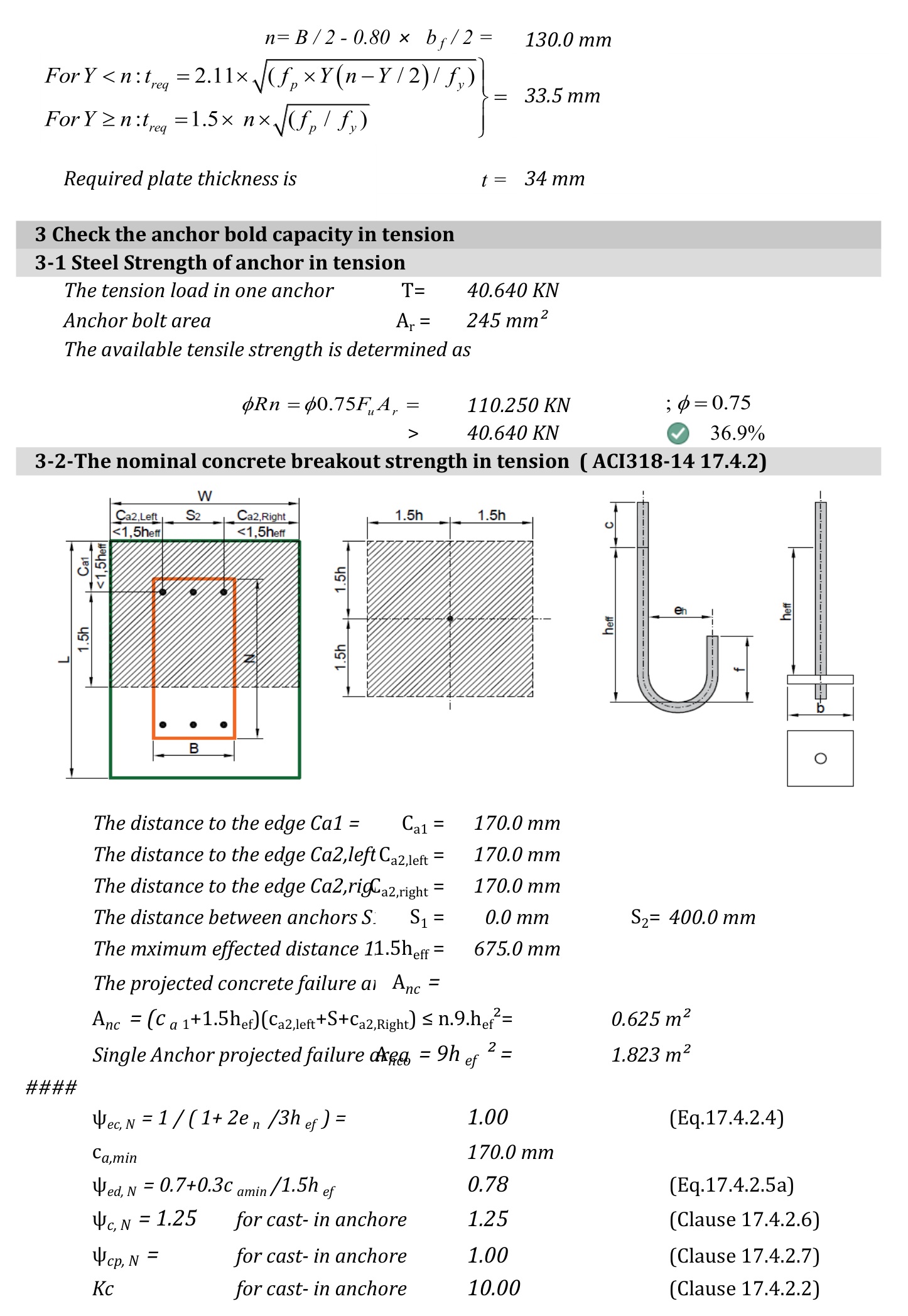
Cast-in headed anchor rods resisting tension Tu are verified for three distinct limit states codified in ACI 318-19 Section 17.4:
- Steel Strength in Tension (ACI 318 17.4.1): phi_sa * Nsa = 0.75 * n_bolts * A_se * Futa, checking tensile yielding and fracture across threaded root area.
- Concrete Breakout Strength (ACI 318 17.4.2): phi_cb * Ncbg evaluating the 35-degree projected failure prism area Anc relative to a single anchor area Anco = 9 * hef^2, with modification factors for edge effects (psi_ed,N), cracked concrete (psi_c,N), and split control (psi_cp,N).
- Anchor Pullout Strength (ACI 318 17.4.3): phi_p * Npn = 0.70 * psi_c,P * 8 * Abrg * f’c, verifying bearing stress on the anchor bolt head or plate washer.
5. Shear Transfer & Combined Interaction Verification
Horizontal shear loads (Vu) transmitted to the foundation are resisted through anchor shear mechanisms. The calculation performs independent verifications for:
- Steel Shear Strength (ACI 318 17.5.1): phi_v * Vsa = 0.65 * n_bolts * 0.60 * A_se * Futa.
- Concrete Shear Breakout (ACI 318 17.5.2): phi_vc * Vcbg accounting for parallel and perpendicular foundation edge distances Ca1 and Ca2, projected shear area Avc, and cracked concrete factors.
- Concrete Pryout Resistance (ACI 318 17.5.3): phi_cp * Vcpg = 0.70 * k_cp * Ncbg, where k_cp = 2.0 for deep embedment (hef >= 65 mm).
Combined Tension-Shear Interaction Formulation
In accordance with ACI 318 Section 17.6, anchor groups resisting simultaneous shear and tensile forces are checked against the tri-linear or 5/3 elliptical interaction criterion:
( Nua / (phi * Nn) )^(5/3) + ( Vua / (phi * Vn) )^(5/3) <= 1.00
The spreadsheet evaluates both the Maximum Tension governing condition and the Maximum Shear governing condition to ensure structural compliance across all load combinations.
6. Calculation Verification Summary Matrix
| Check Item | Demand (Applied) | Capacity (Design phi*Rn) | Design Ratio | Status |
|---|---|---|---|---|
| Concrete Bearing Pressure | fp = 9.87 MPa | q_max = 16.58 MPa | 0.60 | PASSED |
| Base Plate Thickness (tp) | t_req = 34.0 mm | t_prov = 35.0 mm | 0.97 | PASSED |
| Anchor Steel Tensile Strength | Tu = 40.64 kN / bolt | phi*Nsa = 147.0 kN | 0.28 | PASSED |
| Concrete Breakout in Tension | Nua = 121.9 kN (group) | phi*Ncbg = 385.2 kN | 0.32 | PASSED |
| Anchor Pullout Strength | Tu = 40.64 kN / bolt | phi*Npn = 823.2 kN | 0.05 | PASSED |
| Anchor Shear Resistance | Vu = 21.5 kN / side | phi*Vn = 153.2 kN | 0.14 | PASSED |
| Combined Shear-Tension Interaction | (N/Nn)^1.67 + (V/Vn)^1.67 | Limit = 1.00 | 0.18 | PASSED |
7. Step-by-Step Engineering Calculation Workflow
Step 1: Column Profile & Loading Selection
Select standard column shape from the embedded dropdown or input custom plate dimensions (d, bf, tf, tw). Define factored ultimate design forces: axial compression Pu, flexural moment Mu, and shear force Vu.
Step 2: Base Plate & Anchorage Geometry
Establish plate footprint (N x B), trial plate thickness tb, anchor bolt diameter, bolt quantity per side, and anchor spacing coordinates. Enter pedestal dimensions and clear edge distances.
Step 3: Moment Eccentricity & Bearing Evaluation
The sheet computes eccentricity e = Mu / Pu and compares with e_crit. Solves the quadratic equilibrium formulation to establish equivalent bearing length Y and anchor tension Tu.
Step 4: Plate Thickness & Anchorage Verification
Determines minimum required plate thickness tp against AISC DG1 cantilever sections m, n, and n’. Simultaneously executes full ACI 318 Chapter 17 tension, shear, pryout, and interaction checks.
8. File Architecture & System Compatibility
File Format: Microsoft Excel Macro-Enabled Workbook (.XLSM) packaged in a clean .ZIP archive.
Macro Usage: Automation routines assist section table lookups and geometric parameter resets. Core engineering formulas reside directly in transparent cell formulas with zero password protection or hidden locks.
Compatibility: Fully operational in Microsoft Excel 2016, 2019, 2021, and Microsoft 365 (Windows & macOS). No external plugins or commercial add-ins required.
Delivery: Immediate virtual digital download via high-speed instant secure direct digital download immediately following checkout.
Related Products
Spreadsheets
VERIFIED DIGITAL FILE
Instant access
Composite Steel Beam & Slab Design – AISC
Excel checks for a composite steel beam supporting a reinforced concrete slab: pre-composite capacity, shear studs,…

Spreadsheets
-31% OFF
VERIFIED DIGITAL FILE
Instant access
Excel Files - Fire Protection Design according to Eurocode
Nine Excel modules for structural fire design to Eurocode 3 and Eurocode 4 — fire resistance…
Spreadsheets
-20% OFF
VERIFIED DIGITAL FILE
Instant access
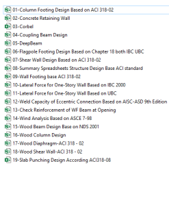
19 ACI 318 Structural Design Excel Templates
19 ready-to-use structural design templates covering foundations, concrete, steel and wood per ACI 318, AISC, IBC,…

Spreadsheets
VERIFIED DIGITAL FILE
Instant access
Steel Pinned Base Plate Design – AISC 360-10
Excel checks for a pinned steel base plate to AISC 360-10: plate capacity under axial, tensile…
Instant Access
39 $