1/6
Spreadsheets
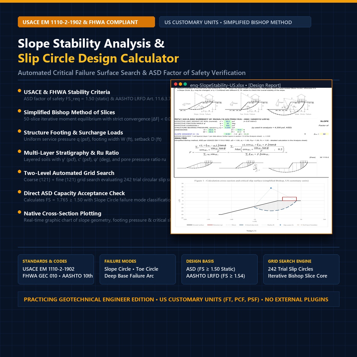
Slope Stability Analysis Excel Calculator (US Customary Units – Simplified Bishop Method & Automated Slip Circle Grid Search)
39 $
Ask AI
What's Included
Geotechnical limit equilibrium calculation spreadsheet performing circular slip surface slope stability analyses conforming to USACE EM 1110-2-1902, FHWA-NHI-05-123 (GEC 010), and AASHTO LRFD Bridge Design Specifications (10th Edition, 2024 Art. 11.6.3.7) in US Customary Units (ft, pcf, psf).
- Simplified Bishop Method of Slices: 50-slice iterative moment equilibrium formulation with convergence tolerance |ΔF| < 0.001.
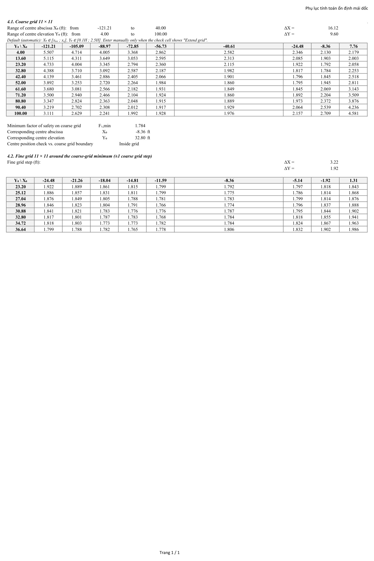
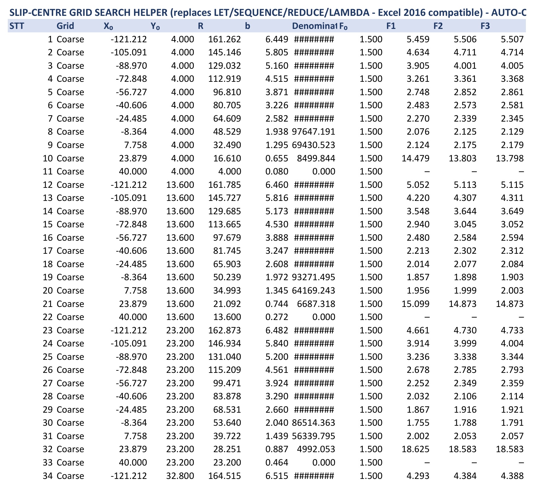
- Automated Slip Circle Grid Search: Two-level search scanning 242 trial circular slip surfaces (11×11 coarse + 11×11 fine) to locate the critical rotation center and minimum Factor of Safety.
- Structural Surcharge & Footing Modeling: Evaluates foundation bearing pressure q (psf), footing width W (ft), and crest setback distance D (ft).
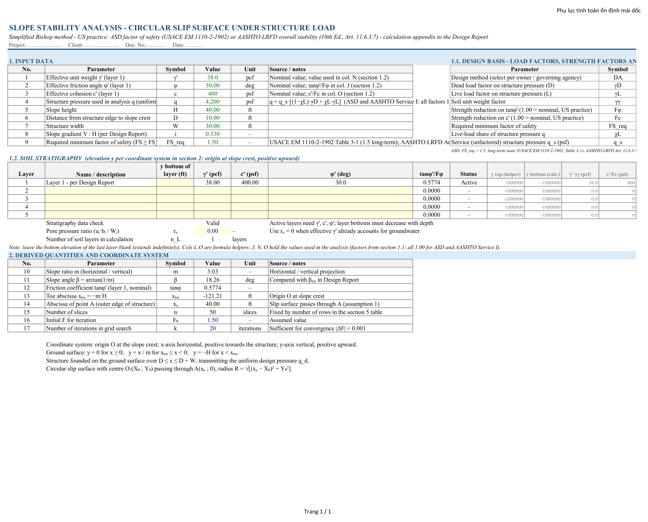
- Multi-Layer Stratigraphy: Profiles with effective unit weight γ’ (pcf), cohesion c’ (psf), friction angle φ’ (deg), and pore pressure ratio ru.
- Failure Mode Classification: Automatic verification for Slope Circle, Toe Circle, and deep-seated Base Circle mechanisms.
- Dynamic Cross-Section Chart: Native Excel scatter plot illustrating slope topography, foundation surcharge, and critical failure arc.
Instant Digital Access
Direct file download immediately after checkout. Access anytime under My Account.
Verified & Standard Compliant
Spreadsheets, tools, and code templates are fully tested for technical accuracy.
Dedicated Support
Direct technical assistance via Telegram @hungthinhvn or Email hangchat.xyz@gmail.com
Product Description
Product Overview
This geotechnical calculation workbook performs limit equilibrium slope stability analyses for circular slip surfaces based on the Simplified Bishop Method of Slices conforming to USACE EM 1110-2-1902, FHWA-NHI-05-123 (FHWA GEC 010), and AASHTO LRFD Bridge Design Specifications (10th Edition, 2024 Art. 11.6.3.7). Formatted in US Customary Units (ft, pcf, psf), the spreadsheet is developed for geotechnical and civil engineers evaluating cut slopes, highway embankments, levee sections, MSE wall backslopes, and foundation slopes supporting surface structural footings. The spreadsheet automates slice discretization, pore pressure modeling, and critical slip circle location via a two-level grid search without requiring external slope stability software.
Governing Standards: USACE EM 1110-2-1902 • FHWA GEC 010 • AASHTO LRFD 10th Ed. • IBC 2024
Calculation Core: Simplified Bishop Method of Slices (50 Slices)
Measurement Units: US Customary (ft, pcf, psf, deg, lb/ft)
Search Engine: 242 Trial Slip Circles (11×11 Coarse + 11×11 Fine)
Format: Pure Excel (.xlsx) • Zero External Macros • Full Formula Visibility
Calculation Core: Simplified Bishop Method of Slices (50 Slices)
Measurement Units: US Customary (ft, pcf, psf, deg, lb/ft)
Search Engine: 242 Trial Slip Circles (11×11 Coarse + 11×11 Fine)
Format: Pure Excel (.xlsx) • Zero External Macros • Full Formula Visibility
Technical Scope & Engineering Capabilities
The spreadsheet incorporates standard limit equilibrium formulations and US geotechnical design criteria organized across structured worksheet modules:
| Module | US Standard Reference | Formulation & Engineering Scope | Acceptance Criteria |
|---|---|---|---|
| ASD & AASHTO Design Basis | USACE EM 1110-2-1902 Table 3-1 AASHTO LRFD Art. 11.6.3.7 | Allowable Stress Design (ASD) factors (γD = 1.0, γL = 1.0, Fφ = 1.0, Fc = 1.0). AASHTO Service I load combination with resistance factor φ = 0.65 (corresponding to FSreq = 1/φ = 1.54). Unfactored soil parameters (γ’, c’, φ’) and service footing pressure q = qs. | FS ≥ 1.50 (ASD) / 1.54 (AASHTO) |
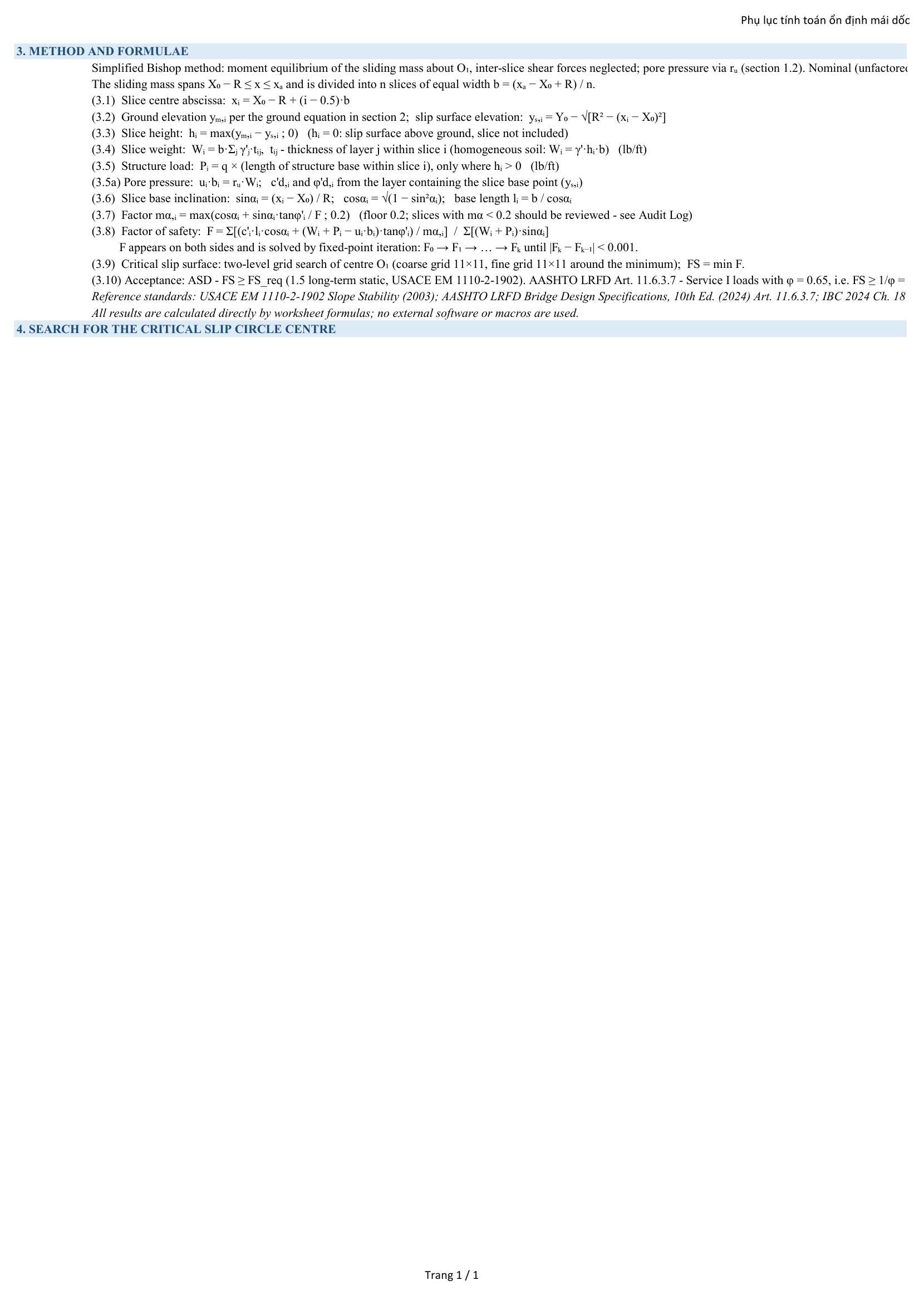
| Simplified Bishop Method | FHWA-NHI-05-123 §6.3 USACE EM 1110-2-1902 App. C | Moment equilibrium formulation satisfying vertical equilibrium for 50 individual vertical slices. Solves iteratively for Factor of Safety F: factor mα,i = cosαi + sinαi·tanφ’i/F with numerical safeguard mα,i ≥ 0.20 until convergence |Fk − Fk−1| < 0.001. | Iterative Moment Equilibrium |
| Two-Level Slip Circle Search | USACE EM 1110-2-1902 §3-3 | Level 1 Coarse Search (11×11 = 121 trial centers) across center range X0 ∈ [xtoe ; xa] and Y0 ∈ [0.1H ; 2.5H]. Level 2 Fine Search (11×11 = 121 trial centers) surrounding the coarse minimum with step increments (ΔX, ΔY) to identify the critical slip circle center (X0, Y0) and radius R. | 242 Trial Slip Circles Evaluated |
| Footing & Surcharge Modeling | IBC 2024 §1808.7 FHWA GEC 010 §6.4 | Models uniform structure bearing pressure q (psf) founded on the slope crest over interval D ≤ x ≤ D + W. Adds vertical line load Pi (lb/ft) to slices intersecting the structure footprint where slice height hi > 0, evaluating destabilizing driving moments and stabilizing base normal forces. | Footing Setback D & Width W |
| Multi-Layer Stratigraphy | USACE EM 1110-2-1902 §2-4 | Supports multi-layer soil profiles defined by bottom layer elevations y (ft), effective unit weights γ’ (pcf), cohesion c’ (psf), and friction angles φ’ (deg). Computes slice weight Wi = b·Σ(γ’j·tij) across intersecting soil horizons. Incorporates pore pressure via ratio ru = uibi/Wi. | Layered Soils & Pore Pressure ru |
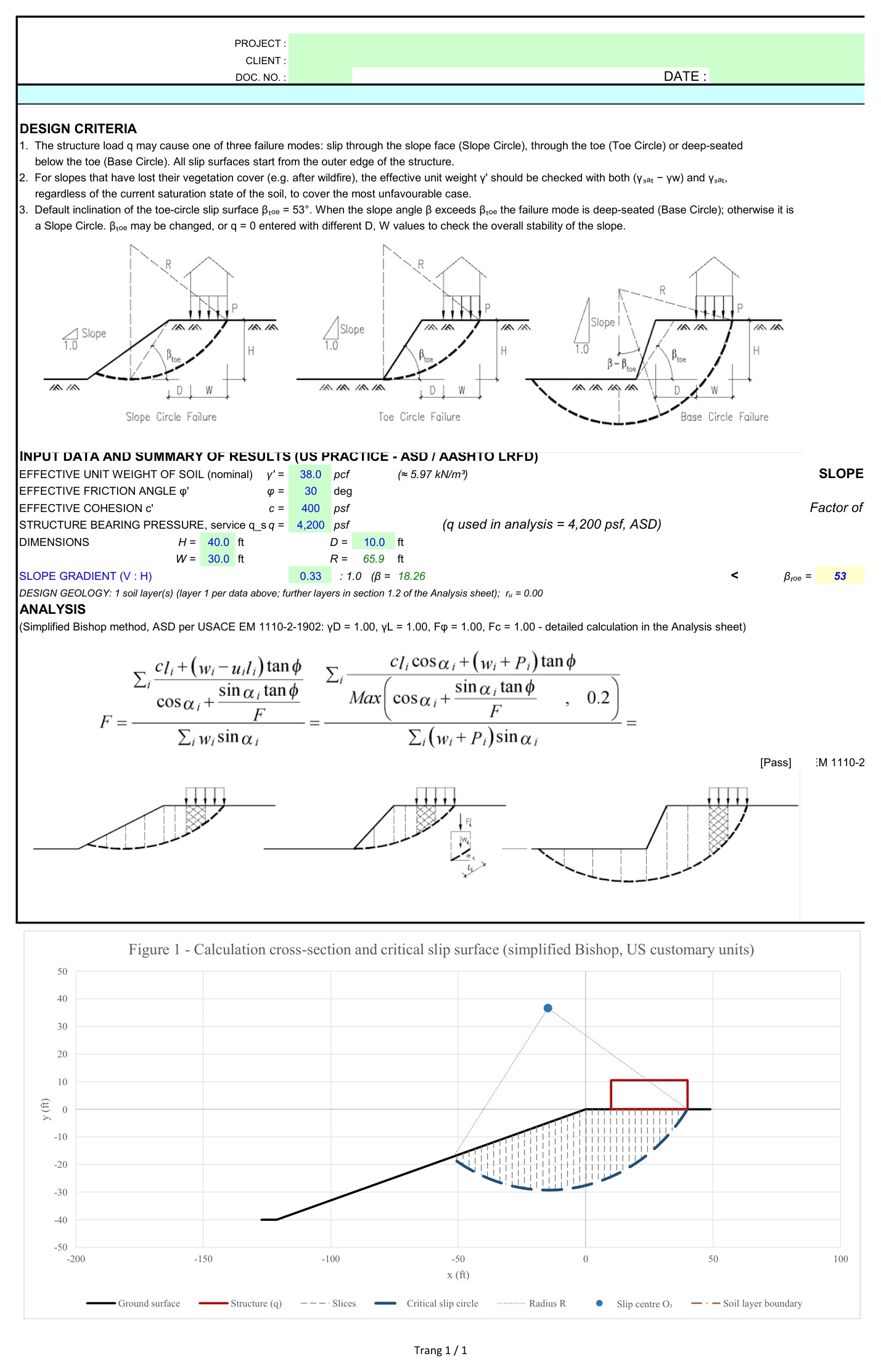
| Summary Verification Output | USACE Table 3-1 / AASHTO | Direct status evaluation comparing calculated Factor of Safety against required factor: FS ≥ FSreq. Returns pass/fail status ([Pass] / [Check]) and reports governing failure mode based on slope angle β versus critical toe angle βtoe = 53°. | FS = 1.765 ≥ 1.50 [Pass] |
Failure Mode Mechanics & Kinematic Criteria
Slope Circle Mechanism
Occurs when the failure arc exits through the slope face above the toe. Governs flatter slopes where the slope angle β is less than the critical toe angle βtoe (default 53°). In the design benchmark: β = 18.26° < 53°, classifying the governing mechanism as a Slope Circle.
Toe Circle Mechanism
Occurs when the circular slip surface passes precisely through the toe of the slope (x = xtoe, y = −H). Characteristic of homogeneous slopes with moderate friction angles and cohesive strength under uniform surcharge loading.
Deep-Seated Base Circle
Occurs when the slip circle passes beneath the toe level into weak foundation strata (y < −H). Governs steep slopes where β > βtoe or where soft cohesive subsoils exist below the embankment foundation elevation.
Native Cross-Section Plotting
Integrated Excel scatter plot displays the ground surface profile, structure surcharge footprint, vertical slice discretization, slip circle center O1(X0, Y0), radius R, and the critical failure arc in true scale without external plugins.
US Geotechnical Reference Standards & DOT Applicability
Formulations, factor of safety thresholds, and load parameters conform to governing geotechnical design standards across US federal, state, and municipal agencies:
| Agency / Standard | Governing Design Code | Geotechnical Criteria & Factor of Safety Requirements |
|---|---|---|
| USACE (U.S. Army Corps of Engineers) | USACE EM 1110-2-1902 (2003) | Table 3-1: Long-term static factor of safety FS ≥ 1.50 for dams, levees, and slopes supporting critical infrastructure; FS ≥ 1.30 for end-of-construction conditions. |
| FHWA (Federal Highway Administration) | FHWA-NHI-05-123 / GEC 010 | Highway cut slopes, bridge approach embankments, and reinforced slopes: recommended static FS ≥ 1.30 to 1.50 depending on risk and structure proximity. |
| AASHTO Highway & Bridge Practice | AASHTO LRFD (10th Ed., 2024) | Article 11.6.3.7 Overall Stability: Evaluated using Service I load combination with resistance factor φ = 0.65 (where geotechnical parameters are based on limited site investigation), requiring equivalent FS ≥ 1/φ = 1.54. |
| State DOTs (Caltrans, TxDOT, NYSDOT) | State Geotechnical Design Manuals | Caltrans GDM Section 8, TxDOT Geotechnical Manual Ch. 5, NYSDOT GDM Ch. 7: Static global stability factor of safety FS ≥ 1.30 to 1.50 for retaining wall backslopes and bridge abutment embankments. |
| Building Codes (IBC / ASCE) | IBC 2024 • ASCE 7-22 | IBC Section 1808.7 Foundation Setback from Slopes: Footing setback requirement of H/3 from slope face and H/2 toe clearance, with global slope stability analysis required where foundation encroachments occur. |
Worksheet Layout & Calculation Screenshots
Calculation views exported directly from the calculation sheets:
Spreadsheet Notes & Engineer Responsibility
- Standard Compliance: Formulated in compliance with USACE EM 1110-2-1902, FHWA-NHI-05-123, and AASHTO LRFD (10th Edition, 2024). Governing code editions and regional requirements should be confirmed with the local authority having jurisdiction.
- Software Requirements: Requires Microsoft Excel 2016 or newer. Compatible with Microsoft 365, Excel 2019, and Excel 2021. Built entirely with standard native worksheet functions without external macros or plugins.
- Circular Slip Surfaces: Evaluates circular failure surfaces via the Simplified Bishop Method. For planar failure modes, thin translational slides along bedrock interfaces, or wedge mechanisms, alternative limit equilibrium methods (such as Spencer or Morgenstern-Price) should be consulted.
- Engineering Judgment: Calculation spreadsheets serve as analytical design aids. Subsurface soil parameters, groundwater assumptions, and factor of safety criteria must be evaluated and validated by a licensed Professional Engineer (PE) or geotechnical specialist.
Package Contents
- Archive File:
Slope-Stability-Analysis-Calculator-US-Units.zip(3.20 MB) - Calculation Workbook:
Slope Stability Analysis US Customary Units.xlsx(8.87 MB uncompressed) - Delivery: Instant Google Drive direct download link provided upon checkout.
Customer Reviews
0.0
Based on 0 reviews
5★
0
4★
0
3★
0
2★
0
1★
0
No reviews yet. Be the first to review this product!
Write a ReviewRelated Products
Spreadsheets
VERIFIED DIGITAL FILE
Instant access
Composite Steel Beam & Slab Design – AISC
Excel checks for a composite steel beam supporting a reinforced concrete slab: pre-composite capacity, shear studs,…

Spreadsheets
VERIFIED DIGITAL FILE
Instant access
Collection of 20 Excel Sheets for HVAC in one single file
20 HVAC Excel sheets in one file: ventilation rate, heating and cooling loads, duct sizing, pressure…
Spreadsheets
-31% OFF
VERIFIED DIGITAL FILE
Instant access
Smart Google Sheet Tracking Crypto Money Flow Hourly
Google Sheet that tracks crypto money flow with hourly Bitcoin on-chain data, automated netflow calculations (inflow…

Spreadsheets
-48% OFF
VERIFIED DIGITAL FILE
Instant access
Automated Gantt Chart Template in Google Sheets
Turn Google Sheets into a fully automated project planner: dynamic Gantt chart, task tracking and progress…
Instant Access
39 $